Modifying UPM Base unit
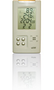
UPM manufactures wireless thermometers and weather stations. The temperature sensors communicate via a radio protocol with the base station.
The protocol sent from the sensors is actually a digital protocol which is AM decoded over 433.92MHz radio signal. The bit rate of the protocol is slow enough to be sampled by the microphone input of a regular PC, so this is the interface we use. All we need is to find the decoded radio signal, adapt the level and feed it into the microphone input. The NetHome software does the rest.
Modifying hardware
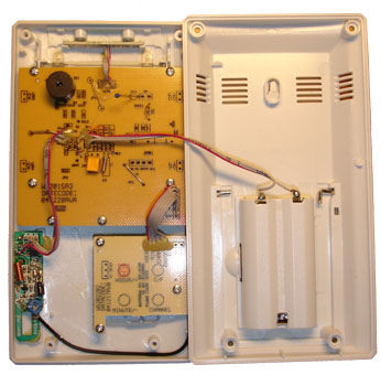
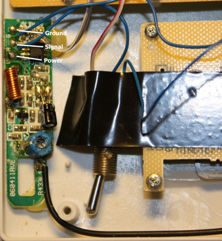
When we open the base unit, we see that UPM has made it easy for us, the radio receiver unit is a separate card (down to the left) where the decoded radio signal is avaliable! There are only three wires connected to the radio board, Power, Ground and signal output. The signal is the decoded digital signal pulses from the transmitters!
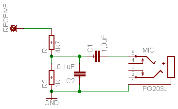
All we have to do is to adapt the signal level of the decoded signal to the microphone input and mount a 3,5mm microphone connector to the UPM case. The circuit needed to adapt the signal is the following:
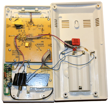
The circuit lowers the level of the signal, the capacitor C1 removes the DC-component of the signal and C2 filters interference. The circuit is so simple, so we do not need any board to mount it on. We can free mount the components on the 3.5mm jack on the inside. This is not pretty, I am sure you can do it nicer.
One thing to note here is that the UPM-unit works hard on saving the battery. When it is switched on, it scans for transmitters for a couple of minutes. After that is switches off the receiver, and only switches it on when it expects a new signal. In this circuit I have choosen to feed the receiver constantly, so I can receive any signals on the 433.92 MHz band. This limits the battery life. In the picture I have actually added a switch so I can choose if I want the receiver on allways or when the UPM-unit needs it. If you only are going to use it as an interface to the temperature sensors, my advise is to leave the power to the radio board as it is, and just connect to the signal output.
The easiest way to connect to the radio receiver is to carefully heat the current cabel connection points and add our cable. Look at this detail picture:
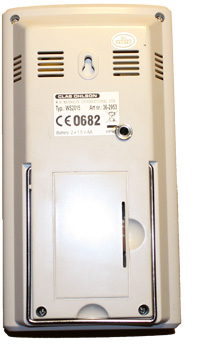
The uglyness of the mod is covered when we close the case, and only the 3.5mm jack is visable on the back:
Now we have a nice computer interface to the UPM-Unit.
Connecting
There are some things to note regarding the placement of the base unit. The radio receiver is quite sensitive to interference, so you should place it at least two meters away from the computer or other RF emitting equipment (WLAN transmitter an such things). You may also have to put a ferrite bead on the cable close to the UPM-Unit to block high frequency interference from other devices.
Microphone settings
The microphone input should be set on highest input “volume” but any microphone boost or AGC should be turned off.
In windows this is done from the control panel under sound settings.
In Linux this is done with the program alsamixer. Start alsamixer from a command prompt (sudo alsamixer) and press F5 to see microphone settings. Use Right and left arrow to move to the “Mic Capt”-level and use up arrow to increase gain.
